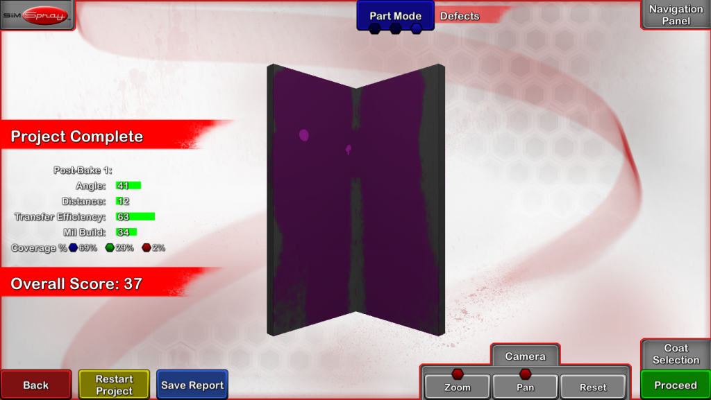
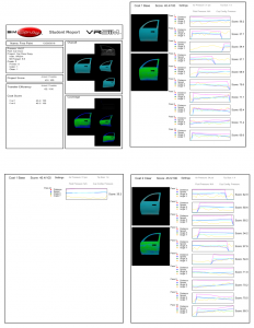
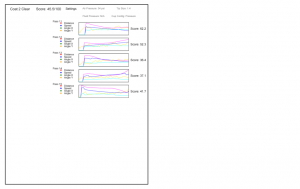
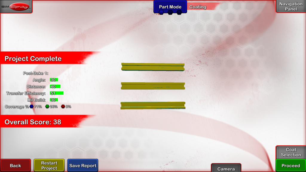
Users receive Scores based on how well they perform important skills. Scores for each skill reflect how closely Users performed the skill as compared to Project Target values. The maximum Score Users receive for a Skill, Coat, Project, or Lesson is 100.
Note: Transfer Efficiency is also Scored 0 to 100, meaning it is possible to get 100 if you get all or almost all material on the part.
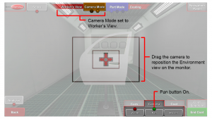
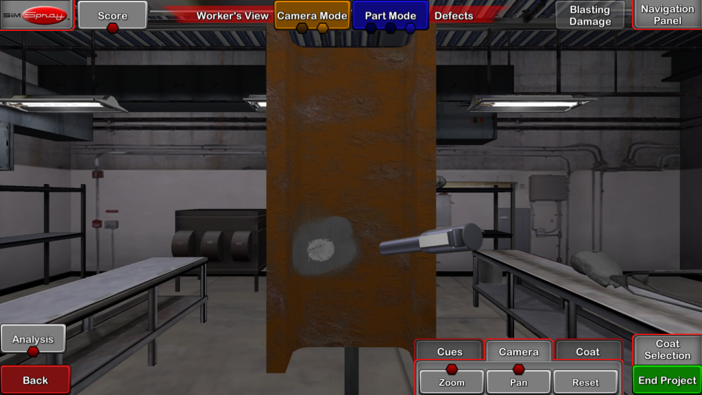
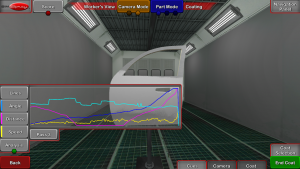
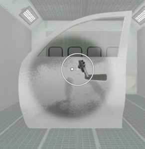
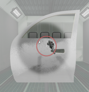
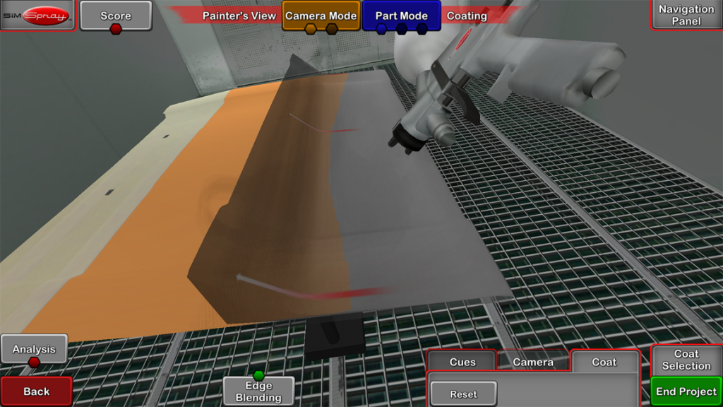
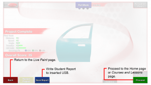
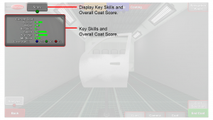
Users can view their Score by tapping the Score button on the Live Scene.
Users receive a Project Score on the Project Review page once they have completed all Coats.
Scored Regions
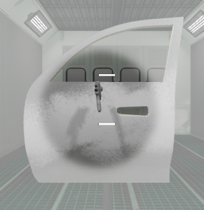
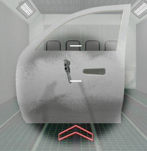
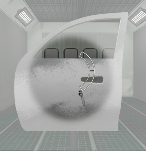
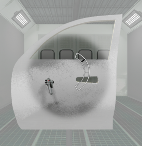
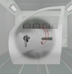
Certain areas of the virtual Part are expected to be Painted, Blasted, or Powder Coated. Other areas are not.
Scored regions have a clean surface, while unscorable regions have an unclean surface.
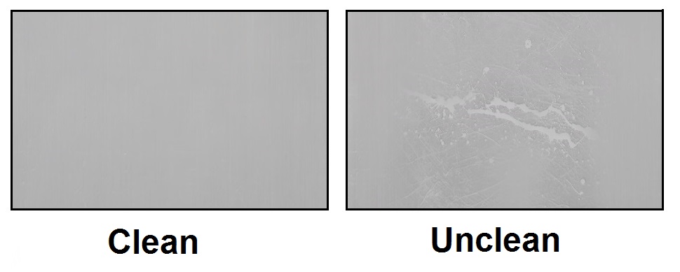
Painting in an unclean surface decreases Transfer Efficiency (wastes material) and does not increase the Mil Build Score. Angle, Distance, and Speed will be Scored on both surfaces.
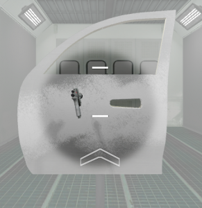
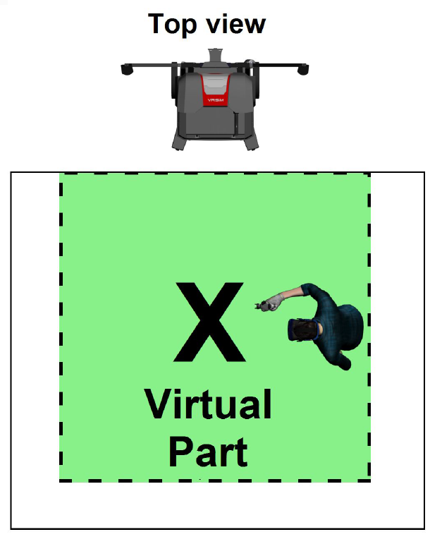
If you are facing the front of the SimSpray unit with your HMD on, clean surfaces can be found in the following areas:
- Paint or blast:
- The right facing side of most parts.
- The top of most horizontal parts.
- Powder coat:
- The full part (in the Electrostatic Booth Environment).
- The right facing side (in the Electrostatic Conveyor Environment).
Paint Score
Paint Users are scored on the following skills for each Paint Coat:
- Overall (Skills Scores Average)
- Angle
- Distance
- Speed
- Transfer Efficiency
- Mil build
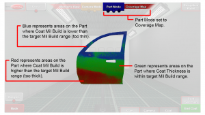
- Coverage % Thin, Ideal, and Thick
The Project Score factors in all Coat Scores and evaluates the total Mil Build across all Coats against the total Mil Build Target.
Transfer efficiency decreases where paint is wasted, either off the Part or in too much mil build (red coverage areas).
Blast Score
Blast Users are scored on the following skills for a Project:
- Overall (Skills Scores Average)
- Angle
- Available starting in v3.1.x software.
- Distance
- % Dirty
- % Clean
- % Damaged
Powder Coat Score
Powder Coat Users are scored on the following skills for a Project:
Pre-Bake
- Overall (Skills Scores Average)
- Angle
- Distance
- Transfer Efficiency
- Mil build
- Coverage % Thin, Ideal, and Thick
Post-Bake (Overall Project Scores)
- Overall (Skills Scores Average)
- Angle
- Distance
- Transfer Efficiency
- Mil build
- Coverage % Thin, Ideal, and Thick