Category Archives: Feedback Tools

Feedback and Tools Overview

Feedback and Tools available in the Live Scene assist in quickly developing their Paint, Blast and/or Powder Coat skills.  

Users have the ability to:

In-Sim Tablet Controls

Overview

Note: requires 3.x software.  See Versions.  Available starting in v3.x software.

The In-Sim Tablet makes it easy to do common actions while keeping the HMD (helmet) on. The Tablet is a moveable, dockable control ‘tablet’ that lets the User access project controls and performance feedback while staying immersed in the training environment.

Positioning

By default, the Tablet will follow and reposition based on the User’s position. The Tablet will typically be found docked on the closest of the four walls of the tracking environment. Note that the User will normally need to turn around to see the Tablet.  Also note that if you do not see the Tablet, then move closer to one of the walls until the Tablet appears.

To reposition the Tablet in a fixed location, aim the Gun over the left or right side of the Tablet, the virtual Gun will change to a hand, pull and hold the Gun trigger to grab the Tablet, move the Gun to reposition the Tablet, and release the Gun trigger to let go of the Tablet.

To redock the Tablet to the side walls, point the Gun at any of the ‘Return’ boxes located on the walls.

Controls

  1. Coating – View Coating Mode.
  2. Coverage Map – Enable or disable Coverage Map Mode.
  3. Defects – View Defects. Select the defect to highlight from a secondary menu. Note: defect selection is limited to applicable defects in the selected process.
  4. Angle – Enable or disable the Angle Cue.
  5. Distance – Enable or disable the Distance Cue.
  6. Speed – Enable or disable the Speed Cue.
  7. Controls shown here are dictated by the selected processes. These controls include:
    Conveyor Speed – Adjust the conveyor line speed. Note: this is only visible in the conveyor environment.Edge Blending – Enable or disable the Edge Blending Cue. Note: this is only visible in the HVLP Edge Blending process.
  8. Remove One – Remove the current Coat.
  9. Remove All – Remove all Coats.
  10. Equipment Settings – Adjust Equipment Settings, including Tip Size, Pressures, and part height location.
  11. Lines – Enable or disable 3D line replay of Gun movement.
  12. End Coat / Project – End the current Coat. If on the last Coat, this ends the Project. Note: in the conveyor environment, use this button to also start the conveyor line.
  13. Coat Selection – Use the left and right arrows to view the information (Score, Coating, Coverage, 3D lines, Defects) of the ‘previous’ or ‘next’ Coat(s).

To learn more about these controls, see the following support articles for more details:

Score

Users receive Scores based on how well they perform important skills. Scores for each skill reflect how closely Users performed the skill as compared to Project Target values. The maximum Score Users receive for a Skill, Coat, Project, or Lesson is 100.

Note: Transfer Efficiency is also Scored 0 to 100, meaning it is possible to get 100 if you get all or almost all material on the part.

Users can view their Score by tapping the Score button on the Live Scene.

Users receive a Project Score on the Project Review page once they have completed all Coats.

Scored Regions

Certain areas of the virtual Part are expected to be Painted, Blasted, or Powder Coated.  Other areas are not.

Scored regions have a clean surface, while unscorable regions have an unclean surface.

Painting in an unclean surface decreases Transfer Efficiency (wastes material) and does not increase the Mil Build Score.  Angle, Distance, and Speed will be Scored on both surfaces.

If you are facing the front of the SimSpray unit with your HMD on, clean surfaces can be found in the following areas:

  • Paint or blast:
    • The right facing side of most parts.
    • The top of most horizontal parts.
  • Powder coat:
    • The full part (in the Electrostatic Booth Environment).
    • The right facing side (in the Electrostatic Conveyor Environment).

Paint Score

Paint Users are scored on the following skills for each Paint Coat:

  • Overall (Skills Scores Average)
  • Angle
  • Distance
  • Speed
  • Transfer Efficiency
  • Mil build
    • Coverage % Thin, Ideal, and Thick

The Project Score factors in all Coat Scores and evaluates the total Mil Build across all Coats against the total Mil Build Target.

Transfer efficiency decreases where paint is wasted, either off the Part or in too much mil build (red coverage areas).

Blast Score

Blast Users are scored on the following skills for a Project:

  • Overall (Skills Scores Average)
  • Angle
    • Available starting in v3.1.x software.
  • Distance
  • % Dirty
  • % Clean
  • % Damaged

Powder Coat Score

Powder Coat Users are scored on the following skills for a Project:

Pre-Bake

  • Overall (Skills Scores Average)
  • Angle
  • Distance
  • Transfer Efficiency
  • Mil build
    • Coverage % Thin, Ideal, and Thick

Post-Bake (Overall Project Scores)

  • Overall (Skills Scores Average)
  • Angle
  • Distance
  • Transfer Efficiency
  • Mil build
    • Coverage % Thin, Ideal, and Thick

Camera Mode

Camera Mode allows Users to change the view displayed on the Monitor during the Live Scene. Users can switch to view what Users see in the moving FMD (Painter’s View) or display a fixed view of the Part centered in the Environment (Worker’s View) on the Monitor.

Users can zoom and pan the environment in Worker’s View.

Painter’s View

Painter’s View displays on the Monitor what Users see in the FMD (Face Mounted Display).

Worker’s View

Worker’s View is a fixed view of the Part centered in the Environment.

Rotate

Users can rotate the Part by dragging the Part with their finger across the touch screen monitor.

Camera

Camera options are available in Worker’s View.  Users can Zoom and Pan the view on the monitor or Reset the view to the default Worker’s View.

Zoom

To Zoom into the Part in Worker’s view, tap the Camera button then toggle the Zoom button.  When the Zoom button is on, the Zoom Bar is displayed, and Users can slide the bar to Zoom the view in or out.

Pan

To Pan in Worker’s View, tap the Camera button then toggle the Pan button.  When the Pan button is on, the Pan Camera Box is displayed and Users can drag the camera to reposition the view on the Monitor.

Reset

To Reset Worker’s View, tap the Camera button then tap the Reset button.  The Reset button recenters the view on the Monitor.

Part Mode

Part Mode provides Users the ability to view the Coverage Map, Coat Defects and the Part Coating as it appears to the naked eye.  Select a Part Mode by toggling the Part Mode button.

The Part Mode button is available in the Live Scene and Review page.

Coating

Coating Part Mode displays the Part as it would appear to the naked eye.  A Part that has no Coats will appear bare.  A Part with one or more painted Coats will appear in the selected Paint Color.  Toggle the Part Mode button to view the Coating.

Coverage Map

The Coverage Map uses colors to display paint Coat thickness as it relates to the Project Coat Settings.  Green represents areas on the Part where Coat thickness is within Target Mil Build Range.  Blue represents areas on the Part where Coat Mil Build is lower than the target Mil Build Range (too thin) and Red represents areas on the Part where Coat Mil Build is higher than the target Mil Build Range (too thick).  Toggle the Part Mode button to view the Coverage Map.

Defects

Toggle the Part Mode button to Defects to view Defects. Highlighted areas on the Paint, Blast, or Powder Color indicate Defects, while darkened areas indicate areas with no Defects.

Paint Defects

Toggle the Part Mode button to Defects then toggle the Defects button to view:

  • Dry Spray
  • Orange Peel
  • Drips

Dry Spray

The Dry Spray Defect occurs when the Paint Gun is too far from the Part or is too off angle.

Orange Peel

The Orange Peel Defect occurs when the spray gun is too far from the Part.

Drips

The Drips Defect occurs when the Paint build up becomes too great.  This can occur if the Paint Gun is too close to the Part, the Paint Gun travels too slowly in front of the Part, or a combination of both.

Drips

The Drips Defect occurs when the Paint build up becomes too great.  This can occur if the Paint Gun is too close to the Part, the Paint Gun travels too slowly in front of the Part, or a combination of both.

Blast Defects

Toggle the Part Mode button to Defects to view Blasting Damage.

Blasting Damage

The Blasting Damage Defect occurs when an area is excessively blasted.  This can occur if the Blast Gun blasts one location for too long.  Blasting Damage occurs more quickly the closer the Blast Gun is to the part.  Blasting Damage can occur when using Garnet and Steel Grit but does not occur with Sodium Bicarbonate.

Powder Coat Defects

Toggle the Part Mode button to Defects from the Project Review page (Post Bake) to view Orange Peel and Sags.

Orange Peel and Sags

The Orange Peel and Sags Defect occurs when the Paint build up becomes too great.  This can occur if the Powder Gun is too close to the Part, the Gun travels too slowly in front of the Part, or a combination of both.

Gun Pass Analysis

Analysis provides in-depth visual feedback on gun pass technique.  Users can view Analysis by tapping the Analysis button on the Live Paint page.

Lines

3D lines and real-time gun movement follow the path of each gun pass so Users can view the gun angle to the Part, gun distance from the Part and gun travel speed for each pass per coat.  Toggle the Lines button to view or hide 3D lines and real-time gun movement.

Graphs

Color coded graphs compare gun angles, distance from the part, and speed range for each pass against parameters set in the selected Project.  Users want to get their parameters as close to the target, vertical center, as possible.

Angle

Gun Angle is represented on Graphs by two lines: a light blue line representing vertical gun rotation and a dark blue line representing horizontal gun rotation.  The Angle lines are active and visible when the Angle button is bordered in light blue.

Toggle the Angle button to view or hide gun angle analysis for the selected gun Pass.

Distance

Distance is represented on Graphs as a magenta line.  The Distance line is active and visible when the Distance button is bordered in magenta.

Toggle the Distance button to view or hide gun distance analysis for the selected gun Pass.

Speed

Speed is represented on Graphs as a yellow line. The Speed line is active and visible when the Speed button is bordered in yellow.

Toggle the Speed button to view or hide gun speed analysis for the selected gun Pass.

Passes

Toggle the Pass button to select the gun pass to analyze or select ‘All Passes’ to analyze all gun passes.


Cues

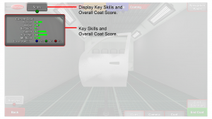
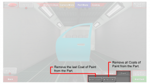
Visual Cues provide Users with in helmet motor skills guidance.  Cues help visually assist Users with gun angle, distance and speed movements.

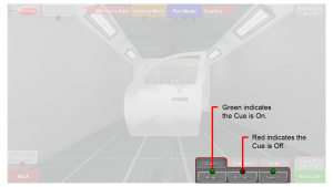
To use a Cue, tap the Cues button then toggle the Cue button On or Off.  Users may turn on any combination of Cues.
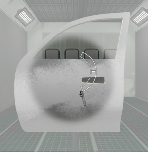
Angle

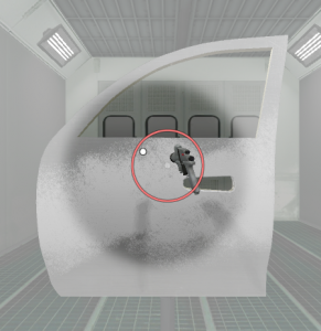
The Angle Cue assists Users in controlling gun angle as they Paint or Powder Coat.

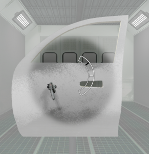
When the Gun orientation matches the Project Target value (optimum orientation), only the Cue target is displayed.

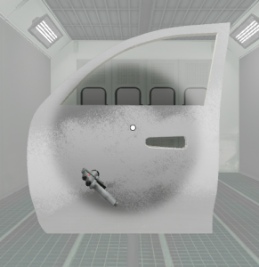
While the Gun orientation is within the Project target range but not in optimum orientation, the Cue target and circle are displayed in white.

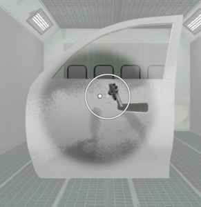
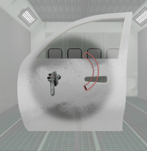
If the Gun orientation is outside the Project target range, the Cue target and circle are displayed in red.

Tap the Cues button then tap the Angle button to toggle the Angle Cue On.

Available starting in v3.1.x software:

  • The Angle Cue will show red in Blasting if the Gun orientation is either too small or too large.

Distance

The Distance Cue assists Users in controlling Gun distance from the Part as they Paint, Blast, or Powder Coat.  The target band appears as two white lines.  When an arrow appears above the target band, the User’s Gun is too close to the Part.  The arrow guides the User to move the Gun away from the Part.  When an arrow appears below the target band, the User’s Gun is too far from the Part.  The arrow guides the User to move the Gun closer to the Part.

When the Gun position matches the Project target value (optimum position) only the Cue target band is displayed.

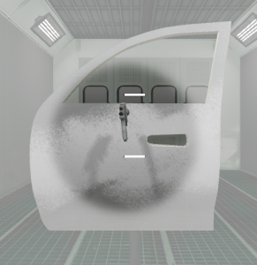
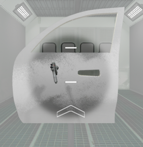
While the Gun position is within the Project target range but not in optimum position, the Cue target band and white arrow are displayed.

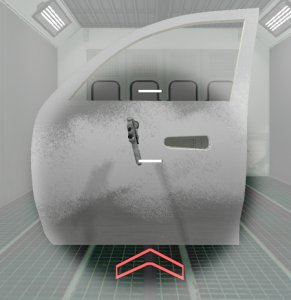
If the gun position is outside the Project target range, the Cue target band and red arrow are displayed.

Tap the Cues button then tap the Distance button to toggle the Distance Cue On.
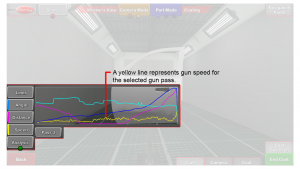
Speed

The Speed Cue assists Users in controlling Gun speed as they Paint.

The Speed Cue is made up of a black speedometer needle and a white target line.

When the Gun speed matches the Project target value (optimum speed), the speedometer needle is on the Cue target line.

While the gun speed is within the Project target range but not at target value, the speedometer needle is near the target line.

If the gun speed is outside the Project target range, the speedometer needle is not near the target line and the speedometer gauge turns red.

Tap the Cues button then tap the Speed button to toggle the Speed Cue On.
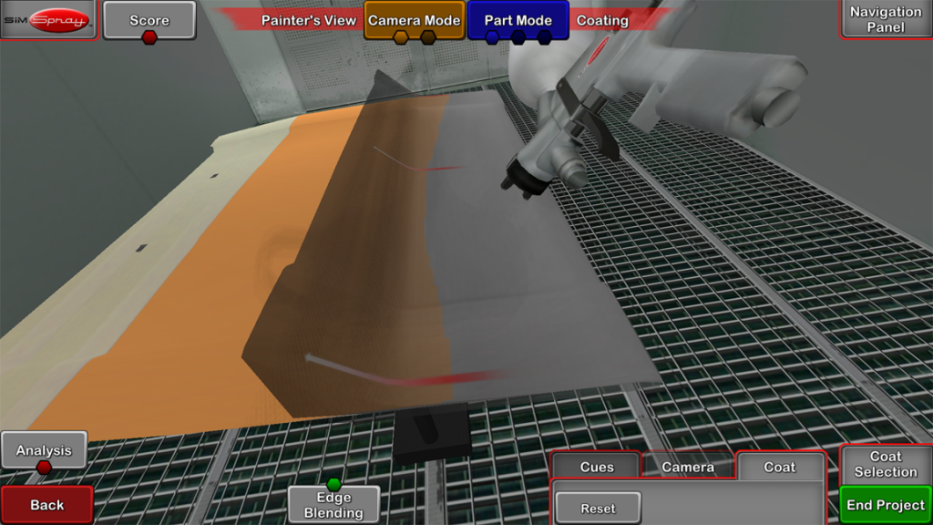
Edge Blending

The Edge Blending Cue assists Users in learning the proper distance and angle necessary for spot and panel painting.  Edge Blending requires Users fan off while blending between the unpainted and already painted sections of the Part.  Users need to stay perpendicular to and the proper distance away from the surface shown of the Edge Blending Cue.

Collision Alerts

Available starting in v2.2.x software.

When the tip of the Gun collides with the virtual Part, a warning sound plays, the Gun stops putting out material, and the Gun rumbles.

Remove Coats & Reset Parts

Users can Remove paint or powder from the Part by tapping the Coat button on the Live Scene then tapping the Remove One button or Remove All button.

One Coat

Tap the Remove One button to remove the current Coat of Paint or Powder from the Part.

If there is only 1 Coat to complete, tap the Reset button.

All Coats

Tap the Remove All button to remove all Coats of Paint or Powder from the Part.