Category Archives: Using SimSpray

Performing Lessons

Lessons provide Users a structured learning environment with defined curriculum goals.  Users select Lessons to perform the associated Activities, Tutorials, and/or Projects.  

The images below describe the workflows Users follow to perform Lessons.  

Users select Lesson Mode from the Modes page.  

Note: Lessons are not available for Blasting in v2.x software. 

To use Curriculum Mode or Lesson Mode:

Software v3.3 introduced “Curriculum Mode” with an online connection to Performance Portal.  This takes the place of the “Lesson Mode”, available in earlier software versions.

  1. Select Curriculum or Lesson on the Modes page then tap the Proceed button.
  2. On the Login page enter your username and password then tap the Proceed button.
  3. First Time Users:  
    • Enter the username and password you want to use.
    • Tap the Proceed button.
    • Tap the Yes button on the Login Failed message box to create your User account. 
  4. Choose a Lesson from the Courses and Lessons page then tap the Proceed button.
  5. Prepare to Paint, Blast or Powder Coat, Perform Tutorials, or Perform Activities.

Preparing To Paint, Blast, or Powder Coat

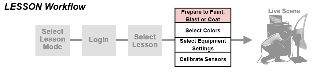
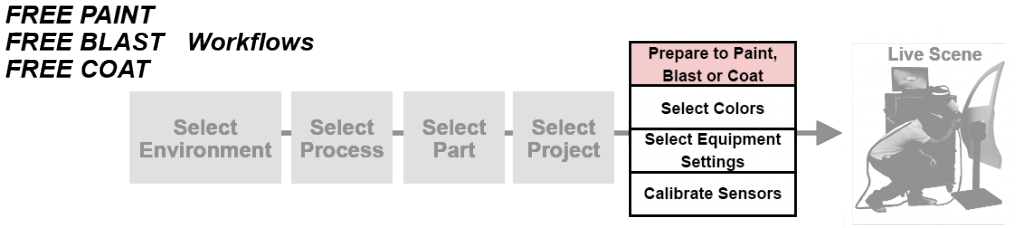
Users need to prepare to Paint, Blast, or Powder Coat their selected Project by:

  • Selecting Colors to use
  • Selecting appropriate Equipment Settings
  • Calibrating motion sensors to track movements

Users will encounter these steps in Free Paint, Free Blast, Free Coat and Lesson Modes and must complete them in order to continue to the Live Scene.


Selecting Colors

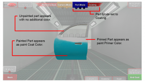
Users select one Color to use for all Primer Coats and one Color to use for all Color Coats in the selected Project.

Selecting Colors to use for a Project is done from the Colors page.

  1. On the Colors page tap a Color to use for Color Coats.
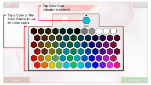
  2. Select the paint finish (matte, semi-gloss, or gloss) for the coat.
    • Available starting in v3.1.x software.
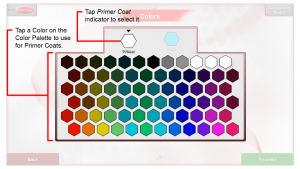
  3. If Primer Coats are included in the selected Project tap the Primer Color indicator then tap a Color to use for Primer Coats.

Selecting or Reviewing Equipment Settings

To Paint or Powder Coat, you must first select Equipment Settings appropriate for the selected Project.  Blast Equipment Settings are preset but are displayed so you can review them.

Note: Equipment Settings are meant to expose Users to proper settings.  With the exception of Tip Sizes, changing the Equipment Settings does not change how the Paint or Powder goes down in the Live Scene.  For Powder Coating, Users can use Faraday Mode in the Live Scene to change how the Powder goes down.

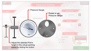
Paint Equipment Settings

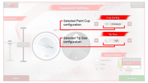
On the Equipment Settings page, rotate the Air and/or Fluid Pressure Dial(s) to set the Pressure Gauge(s) to the selected pressure setting(s) and tap to select a Paint Cup configuration and Tip Size.  Tap the Proceed button.


Paint Tip Sizes

Available in software v2.2 and later:

Selecting a different Tip Size changes the paint flow volume rate for HVLP and the paint flow volume rate and pattern size in Airless and Air-Assisted Airless.

HVLP:

  • 0.5 – 2.5 in intervals of 0.1 (e.g., 0.5, 0.6, 0.7, …, 2.5) (software v3.2 and later)
  • 1.0, 1.2, 1.3, and 1.5 (software v2.2-v3.1.0)

Airless and Air-Assisted Airless:

  • Fan size: 2-15 in intervals of 1 (e.g., 2, 3, 4, …, 15)  (software v3.2 and later)
    Orifice Size: 7 – 35 in intervals of 2 (e.g., 7, 9, 11, …, 35)  (software v3.2 and later)
  • 313, 415, 517, and 614 (software v2.2-v3.1.0)
Live Gun Adjustments

Available in v2.2.x software and later:

When in the environment, adjust the Spray Gun dials for real-time effects.

HVLP

The back, top physical dial on the Gun adjusts the fan pattern size. Increasing the % increases the size.

  • Available in v2.2.x software and later, increasing the size spreads (decreases the thickness of) the paint reaching the Part. The default is set to 100% fan pattern size. Decreasing this knob directly affects and increases the target Travel Speed and Travel Speed Cue.

The back, bottom physical dial adjusts the fluid flow amount. Increasing the % increases the amount of paint.

  • Available in v2.2.x software and later, this knob much more significantly affects the amount of paint. In earlier versions, the fluid flow amount adjusted only slightly. The default is set to 50% fluid amount. Increasing this knob directly affects and increases the target Travel Speed and Travel Speed Cue.

Rotate the front nozzle by 90 degrees to change the pattern orientation between vertical and horizontal.

Air-Assisted Airless

Available in v2.2.x software and later:

The back, bottom physical dial on the Gun adjusts the air amount. Increasing the % increases the amount of the paint reaching the Part. Increasing this knob directly affects and increases the target Travel Speed and Travel Speed Cue.


Amount of Paint

Available in v2.2.x software and later:

To increase the amount of liquid paint going down:

  • All processes (Air-Assisted Airless, Airless, HVLP):
    • Increase the tip size. Adjustable on the Equipment Settings screen.
    • Decrease the travel speed. Adjustable in the Admin Portal.
    • Decrease the distance to the part. Adjustable in the Admin Portal.
  • Air-Assisted Airless:
    • Increase the air amount by opening up (increasing  the % of) the bottom dial. Adjustable in Live Painting.
  • HVLP:
    • Decrease the fan pattern size by closing down (reducing the % of) the top fan pattern dial. Adjustable in Live Painting.
    • Increase the fluid amount by opening up (increasing  the % of) the bottom fluid dial. Adjustable in Live Painting.

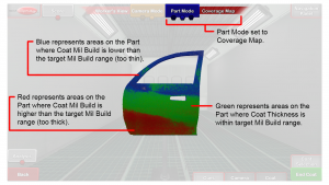
To increase how fast paint builds up in Coverage Map Mode:

  • Follow the above.
  • Decrease the mil target. Adjustable in the Admin Portal.

Blast Equipment Settings

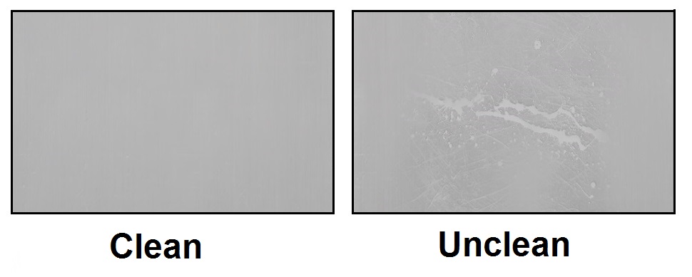
On the Equipment Settings page, review the blast media, damage level and clean rate for the selected Project.  Tap the Proceed button.

Blasting Rate

Available starting in v3.1.x software:

  • The Blasting Gun’s Angle and Distance affect how quickly the paint and rust get blasted away.
  • Rust is removed slower than paint.
  • The overall blasting rate was increased from previous versions.

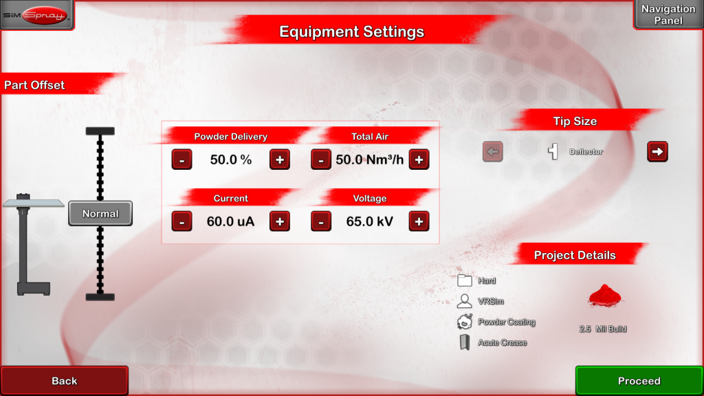
Powder Coat Equipment Settings

On the Equipment Settings page, select the desired settings and Tip Size.  Tap the Proceed button.

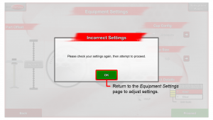
Incorrect Equipment Settings

Attempting to use Equipment Settings outside of the acceptable Equipment Setting Ranges prevents continuing beyond the Equipment Settings page and into the Live Scene.

Equipment Settings for Default Projects can be found on the Default Projects list.  See Managing Projects for Custom Projects.
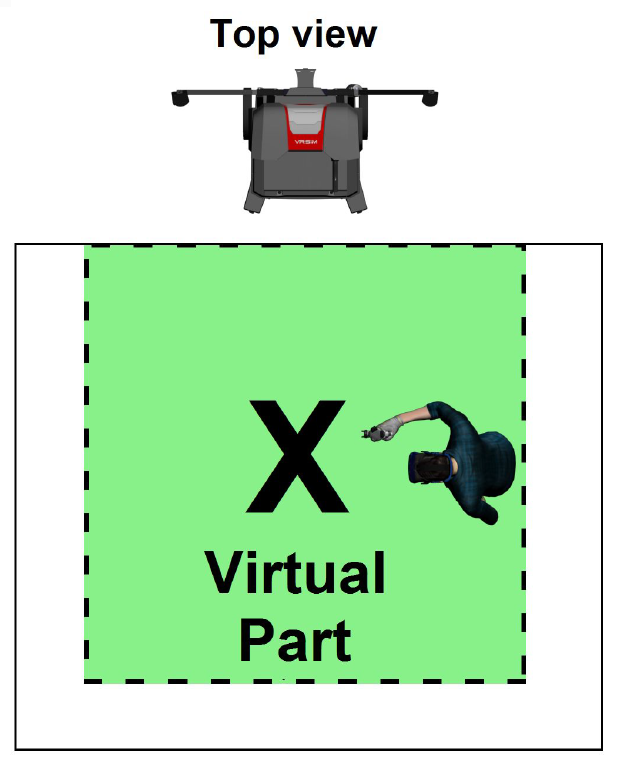
Calibrating Sensors

A Calibration process is necessary to align all tracking sensors before entering the Live Scene.  The Calibration process takes place on the Calibration page.

Users will arrive at the Calibration page from the Equipment Settings page. Follow the onscreen instructions to perform the Calibration process.

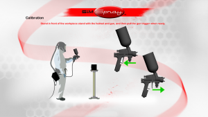
Note: as indicated on the touch screen, you will need to stand still during Calibration.  When complete the Live Scene will appear. Users will be able to view the selected Environment and Part through the FMD and perform the selected Project or Lesson.

See Recalibrate for additional information on how to Recalibrate if the Calibration process was unsuccessful.

Free Paint, Free Blast, or Free Coat

Free Paint, Free Blast and Free Coat Modes give Users the freedom to select and practice Projects anonymously.  Users are guided to the appropriate Pages to Filter, select, and prepare their selected Projects.  Users select from and perform any available Project and receive an anonymous Student Report for completing Projects.  

The image below describes the workflow for Free Paint, Free Blast, Free Coat.

To use Free Paint, Free Blast or Free Coat Mode:

  1. Tap Free Paint, Free Blast or Free Coat Mode on the Modes page and then tap the Proceed button.
  2. Select an Environment from the Environment page by tapping it.  Tap the Proceed button.Note: Selecting a Conveyor Environment allows you to Paint or Powder Coat on moving Parts.

  3. Select a Process from the Processes page by tapping it.  Tap the Proceed button.
  4. Select a Part on the Parts page by tapping it.  Use the Parts Filter to help locate Parts.  Tap the Proceed button.

  5. Select a Project from the Projects page by tapping it.  Tap the Proceed button.

  6. Prepare to Paint, Blast or Free Coat.

Live Scene

Users land on the Live Scene from the Calibration page or the Equipment Settings page. Painting, Blasting and Powder Coating in SimSpray™ are performed in the Live Scene.

Here, Users will work with their chosen Lesson or Part and use Feedback Tools to view, evaluate, and improve their performance.  After doing this, Users End Coat, End Project, or Bake the Part.

End Coat Button

A Paint Coat is considered complete when Users tap the End Coat button.

Opens the Equipment Settings page so Paint Users can select the appropriate settings for the next Coat of their Project.

End Project Button

A Paint or Blast Project is considered complete when Users tap the End Project button. The End Project button appears when Users are Painting or Blasting the final Coat.

The End Project button:

  • Saves the last Coat Scores, gun Passes and Project Scores.
  • Opens the Project Review page.
  • Creates a Student Report for the completed Project and attempts to write it to a USB drive.

Bake Button – Powder Coating

A Powder Coat Project is considered complete when Users tap the Bake button. The Bake button appears when Users are Powder Coating

The Bake button simulates the Powder Coating Bake step and generates Post-Bake Scores.  Post-Bake Coverage and Mil Build Scores may change from Pre-Bake Scores because during the Baking process, paint may spread.

The Bake button:

  • Saves the last Pre-Bake Scores and gun Passes.
  • Performs a Bake step and generates Post-Bake Scores.
  • Opens the Project Review page.

  • Creates a Student Report for the completed Powder Coat Project and attempts to write it to a USB drive.

Faraday Mode

Faraday Mode makes adjustments to the Powder Coat Gun to better handle the Faraday Cage effect.  These changes make it easier to cover internal corners and recesses on a Part.  

Quickly double-tap the Powder Gun’s trigger to toggle Faraday Mode on or off. (Available starting in v2.2.x software)

Otherwise, toggle the Faraday Mode button On in the Live Scene.  This reduces the Powder Coat Gun voltage and powder flow rate.

While in Faraday Mode, the default Powder Gun distance acceptable range increases.  Additionally, angle is not scored while using Faraday Mode.

Feedback and Tools Overview

Feedback and Tools available in the Live Scene assist in quickly developing their Paint, Blast and/or Powder Coat skills.  

Users have the ability to:

In-Sim Tablet Controls

Overview

Note: requires 3.x software.  See Versions.  Available starting in v3.x software.

The In-Sim Tablet makes it easy to do common actions while keeping the HMD (helmet) on. The Tablet is a moveable, dockable control ‘tablet’ that lets the User access project controls and performance feedback while staying immersed in the training environment.

Positioning

By default, the Tablet will follow and reposition based on the User’s position. The Tablet will typically be found docked on the closest of the four walls of the tracking environment. Note that the User will normally need to turn around to see the Tablet.  Also note that if you do not see the Tablet, then move closer to one of the walls until the Tablet appears.

To reposition the Tablet in a fixed location, aim the Gun over the left or right side of the Tablet, the virtual Gun will change to a hand, pull and hold the Gun trigger to grab the Tablet, move the Gun to reposition the Tablet, and release the Gun trigger to let go of the Tablet.

To redock the Tablet to the side walls, point the Gun at any of the ‘Return’ boxes located on the walls.

Controls

  1. Coating – View Coating Mode.
  2. Coverage Map – Enable or disable Coverage Map Mode.
  3. Defects – View Defects. Select the defect to highlight from a secondary menu. Note: defect selection is limited to applicable defects in the selected process.
  4. Angle – Enable or disable the Angle Cue.
  5. Distance – Enable or disable the Distance Cue.
  6. Speed – Enable or disable the Speed Cue.
  7. Controls shown here are dictated by the selected processes. These controls include:
    Conveyor Speed – Adjust the conveyor line speed. Note: this is only visible in the conveyor environment.Edge Blending – Enable or disable the Edge Blending Cue. Note: this is only visible in the HVLP Edge Blending process.
  8. Remove One – Remove the current Coat.
  9. Remove All – Remove all Coats.
  10. Equipment Settings – Adjust Equipment Settings, including Tip Size, Pressures, and part height location.
  11. Lines – Enable or disable 3D line replay of Gun movement.
  12. End Coat / Project – End the current Coat. If on the last Coat, this ends the Project. Note: in the conveyor environment, use this button to also start the conveyor line.
  13. Coat Selection – Use the left and right arrows to view the information (Score, Coating, Coverage, 3D lines, Defects) of the ‘previous’ or ‘next’ Coat(s).

To learn more about these controls, see the following support articles for more details:

Score

Users receive Scores based on how well they perform important skills. Scores for each skill reflect how closely Users performed the skill as compared to Project Target values. The maximum Score Users receive for a Skill, Coat, Project, or Lesson is 100.

Note: Transfer Efficiency is also Scored 0 to 100, meaning it is possible to get 100 if you get all or almost all material on the part.

Users can view their Score by tapping the Score button on the Live Scene.

Users receive a Project Score on the Project Review page once they have completed all Coats.

Scored Regions

Certain areas of the virtual Part are expected to be Painted, Blasted, or Powder Coated.  Other areas are not.

Scored regions have a clean surface, while unscorable regions have an unclean surface.

Painting in an unclean surface decreases Transfer Efficiency (wastes material) and does not increase the Mil Build Score.  Angle, Distance, and Speed will be Scored on both surfaces.

If you are facing the front of the SimSpray unit with your HMD on, clean surfaces can be found in the following areas:

  • Paint or blast:
    • The right facing side of most parts.
    • The top of most horizontal parts.
  • Powder coat:
    • The full part (in the Electrostatic Booth Environment).
    • The right facing side (in the Electrostatic Conveyor Environment).

Paint Score

Paint Users are scored on the following skills for each Paint Coat:

  • Overall (Skills Scores Average)
  • Angle
  • Distance
  • Speed
  • Transfer Efficiency
  • Mil build
    • Coverage % Thin, Ideal, and Thick

The Project Score factors in all Coat Scores and evaluates the total Mil Build across all Coats against the total Mil Build Target.

Transfer efficiency decreases where paint is wasted, either off the Part or in too much mil build (red coverage areas).

Blast Score

Blast Users are scored on the following skills for a Project:

  • Overall (Skills Scores Average)
  • Angle
    • Available starting in v3.1.x software.
  • Distance
  • % Dirty
  • % Clean
  • % Damaged

Powder Coat Score

Powder Coat Users are scored on the following skills for a Project:

Pre-Bake

  • Overall (Skills Scores Average)
  • Angle
  • Distance
  • Transfer Efficiency
  • Mil build
    • Coverage % Thin, Ideal, and Thick

Post-Bake (Overall Project Scores)

  • Overall (Skills Scores Average)
  • Angle
  • Distance
  • Transfer Efficiency
  • Mil build
    • Coverage % Thin, Ideal, and Thick

Camera Mode

Camera Mode allows Users to change the view displayed on the Monitor during the Live Scene. Users can switch to view what Users see in the moving FMD (Painter’s View) or display a fixed view of the Part centered in the Environment (Worker’s View) on the Monitor.

Users can zoom and pan the environment in Worker’s View.

Painter’s View

Painter’s View displays on the Monitor what Users see in the FMD (Face Mounted Display).

Worker’s View

Worker’s View is a fixed view of the Part centered in the Environment.

Rotate

Users can rotate the Part by dragging the Part with their finger across the touch screen monitor.

Camera

Camera options are available in Worker’s View.  Users can Zoom and Pan the view on the monitor or Reset the view to the default Worker’s View.

Zoom

To Zoom into the Part in Worker’s view, tap the Camera button then toggle the Zoom button.  When the Zoom button is on, the Zoom Bar is displayed, and Users can slide the bar to Zoom the view in or out.

Pan

To Pan in Worker’s View, tap the Camera button then toggle the Pan button.  When the Pan button is on, the Pan Camera Box is displayed and Users can drag the camera to reposition the view on the Monitor.

Reset

To Reset Worker’s View, tap the Camera button then tap the Reset button.  The Reset button recenters the view on the Monitor.

Part Mode

Part Mode provides Users the ability to view the Coverage Map, Coat Defects and the Part Coating as it appears to the naked eye.  Select a Part Mode by toggling the Part Mode button.

The Part Mode button is available in the Live Scene and Review page.

Coating

Coating Part Mode displays the Part as it would appear to the naked eye.  A Part that has no Coats will appear bare.  A Part with one or more painted Coats will appear in the selected Paint Color.  Toggle the Part Mode button to view the Coating.

Coverage Map

The Coverage Map uses colors to display paint Coat thickness as it relates to the Project Coat Settings.  Green represents areas on the Part where Coat thickness is within Target Mil Build Range.  Blue represents areas on the Part where Coat Mil Build is lower than the target Mil Build Range (too thin) and Red represents areas on the Part where Coat Mil Build is higher than the target Mil Build Range (too thick).  Toggle the Part Mode button to view the Coverage Map.

Defects

Toggle the Part Mode button to Defects to view Defects. Highlighted areas on the Paint, Blast, or Powder Color indicate Defects, while darkened areas indicate areas with no Defects.

Paint Defects

Toggle the Part Mode button to Defects then toggle the Defects button to view:

  • Dry Spray
  • Orange Peel
  • Drips

Dry Spray

The Dry Spray Defect occurs when the Paint Gun is too far from the Part or is too off angle.

Orange Peel

The Orange Peel Defect occurs when the spray gun is too far from the Part.

Drips

The Drips Defect occurs when the Paint build up becomes too great.  This can occur if the Paint Gun is too close to the Part, the Paint Gun travels too slowly in front of the Part, or a combination of both.

Drips

The Drips Defect occurs when the Paint build up becomes too great.  This can occur if the Paint Gun is too close to the Part, the Paint Gun travels too slowly in front of the Part, or a combination of both.

Blast Defects

Toggle the Part Mode button to Defects to view Blasting Damage.

Blasting Damage

The Blasting Damage Defect occurs when an area is excessively blasted.  This can occur if the Blast Gun blasts one location for too long.  Blasting Damage occurs more quickly the closer the Blast Gun is to the part.  Blasting Damage can occur when using Garnet and Steel Grit but does not occur with Sodium Bicarbonate.

Powder Coat Defects

Toggle the Part Mode button to Defects from the Project Review page (Post Bake) to view Orange Peel and Sags.

Orange Peel and Sags

The Orange Peel and Sags Defect occurs when the Paint build up becomes too great.  This can occur if the Powder Gun is too close to the Part, the Gun travels too slowly in front of the Part, or a combination of both.